Dave's Stuff That Needs To Go Somewhere

If you have a bed probe on your 3D printer, you know that you need to get the right vertical (Z) offset from the nozzle to the probe for it to work properly. If you switch nozzles, you know you need to repeat this, and it can be pretty tedious. Thankfully there's a way to automate this whole process, using the Klipper Z-calibration script, which does the following three steps:

  • Probes a switch with the nozzle
  • Probes the same switch with the bed probe, to tell the difference between the two
  • Probes the bed to get the actual point at which Z is 0

This has been made to work with the Ender 3, but the documentation seems to be both fairly lacking and also largely contained in a difficult to search Discord thread on KevinAkaSam's sandbox. Here I'm attempting to document what I did and what tripped me up along the way. I'm assuming a decent baseline understanding of how 3D printers work and experience with doing mods, beginners will likely get lost here. This is not an authoritative source of documentation, just what I found along the way when doing it myself.

Background

My setup consists of an Ender 3 V2, with the following mods before starting this process:

(I considered making affiliate accounts to link to the products above in the vague hope I might make 20p off it, but the links are clean. Feel free to hire me as compensation instead.)

I think the only necessary part of this is running Klipper. You don't need a replacement board to do it, but you do need a separate computer (e.g. a Raspberry Pi) to run Klipper on, and there are plenty of guides to getting going with that so I won't cover it here. You do also obviously need some kind of bed probe, and the calibration script does assume you're using something Klicky-based, but I think it could work with anything that involves physically touching the bed.

If you have a replacement Y carriage, it may pose an issue if it doesn't have the same rough layout as the stock one, but mine was fine.

Klackender beta detour

I like Klackender, it's a very cheap and simple system for a bed probe, but it is also precise and reliable, certainly compared to my BLTouch once I started having weird issues with it. I did, however, have issues where the probe would sometimes fail to dock straight, and would then be knocked off. When I actually started paying attention to KevinAkaSam's Discord, when I was converting my printer's Z axis to be belt driven, I noticed the #klack-beta channel existed and had a “new” design (from several years ago, it actually existed when I first set up Klackender but I had no idea) that cuts down the size of the probe block, and makes the dock more reliable. I would very much recommend using the beta if you're planning on moving over to Klackender, and the files were recently added to GitHub so you don't need to join the Discord to get them. Hooray! Installation/assembly is basically the same as the non-beta version.

If you, like me, have a Micro Swiss NG extruder, you can use the old style modified probe mount along with my brutal mod to the dock to have it work.

Setting up the Auto Z calibration

There are three parts here: setting up the hardware, configuring the software, then doing some calibration.

Hardware

Again this gets broken down into two pieces; the Voron Z endstop (sexbolt), and the Ender 3-specific parts. There is also a version of the Ender 3-specific parts from KevinAkaSam, which mounts on the X axis instead and uses a different switch setup, but that's in the Discord and not what I used.

For the endstop, I bought a kit from Aliexpress and replaced the microswich it came with with an Omron D2F. If you're doing this mod, you probably want the consistency of a brand name microswitch.

For the Ender 3-specific parts, I printed out the bolt-on version from the GitHub repository, using the “stockE3” variants. I picked the bolt-on version because it seemed like it would be more robust, and it has a space to put a nozzle wipe in, which feels important for getting the right Z offset. Anyway, it turns out this was a mistake, because there's an Ender 3 V2 version in a pinned message in the KevinAkaSam Discord thread. I appreciate that this is work done for free and there's no obligation to do anything, but I maintain that Discord is the worst place to share instructions and files. Even having searched a whole load in the thread for various answers to questions, I only found this out when I'd already assembled all the hardware and was looking for how to configure the software side, basically meaning that for me the work may as well not have been done at all. Unfortunately I don't feel comfortable resharing files that don't have an explicit licence attached to the, so you'll have to join if you want to find them, but at least you know they exist. Anyway, this digression aside, this meant I had to trim a little bit off the mount to avoid it running into the Y limit switch housing.

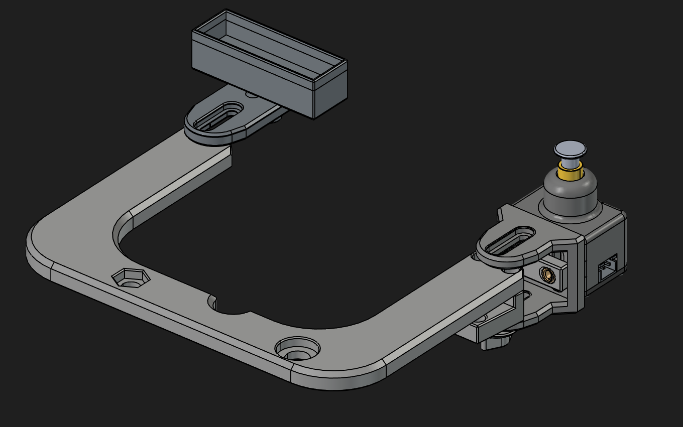
For seeing how the parts are meant to go together, I recommend looking at the relevant .step file using something like FreeCAD. This will also show you where heatset inserts are required, e.g. where the Z endstop is screwed into (yellow in the screenshot below). It won't show you where or what bolts are needed, but I found trying various M3 bolts would get me something that would work. The bolt-on assembly as viewed in FreeCAD

I found positioning the actual endstop to be slightly tricky, and I definitely mounted it ridiculously high, at about 8mm above the bed surface with a normal bed. Still, I don't think it matters too much, as long as the nozzle and probe can hit the endstop, and the endstop housing doesn't slip down when it is hit. A bit of bending is, I think, unavoidable but also not a problem.

You will probably need to cut away some of the top of the Y tensioner (at the front of the printer) to allow the Y carriage to move far enough forwards to let the nozzle hit the switch. I got a bit confused at this point and thought I needed to be able to move fowards even further to be able to hit the switch with my probe, but no, the probe is behind the nozzle which means that the bed also moves backwards to line up the switch with it. I don't know why this caught me out, but it did.

Finally, you'll need to plug the endstop into an arbitrary I/O pin you have free on your board, and to ground. Hopefully you have some spare, I think people often use the bed probe pins since they have their Klackenders wired up to the Z endstop pins.

Software

You need to install the Z calibration script. The wiki has a few options. It also documents the configuration steps pretty well, so I won't go into too much detail here.

You will need to increase position_max in your stepper_y section to be able to hit the endstop. I recommend setting it to, say, 240, then going to 235 and nudging it forward by 1mm at a time until the wheels can't go any further. Once you do this you can figure out the X and Y values needed to hit the switch with the nozzle.

One thing that I struggled to figure out is how the Z endstop pin is configured. Well, turns out you configure the Z endstop as the Z endstop. This probably means you will need to update some other parts of your Klipper config. I suspect that using the proper Klicky macros avoids this, but I'm using basic Klackender ones, and so I had to update:

  • Changing the Z endstop to be a real pin, instead of probe:z_virtual_endstop
  • Adding a position_endstop that roughly corresponded to where it actually is in relation to the bed
  • Temporarily adjusting position_min as I was going through the process of figuring out what height the endstop is actually at
  • Re-adjusting my homing_override to use the new endstop. This is very important! If you don't do this, you'll have the nozzle slowly crash into the middle of your bed and not stop.

My homing_override now looks like this:

[homing_override]
set_position_z:0 # Make printer think Z axis is at zero, so we can force a move upwards away from build plate
gcode:
  G90
  G1 Z10 F3000 ; move up to prevent accidentally scratching build plate    
  G28 X
  G28 Y
  G1 X173 Y238 F6000
  G28 Z
  G1 Z10 F3000
  G1 X0 Y0 F6000

In the above, X173 and Y238 are the values needed to hit the switch with the nozzle.

For completeness, here's my z_calibration section:

[z_calibration]
nozzle_xy_position: 173,238 
switch_xy_offsets: -5,-20
bed_xy_position: 117.5,117.5
switch_offset: 0.091
start_gcode: probe_out
end_gcode: probe_in
offset_margins: -1.8,-0.3

Calibration

I don't think I need to go into any detail here, just acknowledging that you probably do want to alter the switch_offset configuration value via the calibration. I recommend getting feeler gauges to get a good level of precision on your adjustments.

Conclusion

Hopefully this is actually useful to some people. I know it would have been to me. This was a very worthwhile mod once I got it working, since I have a quick-change Revo system but swapping nozzles was always a pain with them needing ever so slightly different offsets from each other.

I didn't cover the nozzle brush here, but that's because what I have at the moment is terrible and I need to figure out a good solution.

If you did find this useful, or have suggestions for changes, it would be nice to hear from you on the fediverse.

Edit: Disregard the following, it's for a different motherboard, which caused me much confusion.

I had been intending to go through and document what pins each port on the Ender 3 v2's motherboard corresponded to on the microcontroller, since I couldn't find it clearly documented anywhere, and that's what this blog post was going to be. Thankfully, via a convoluted path of search results I eventually found a gist on GitHub with them, saving me the work. I'm publishing this post in the vague hope that it might do a tiny little bit to push the search rankings up for that documentation, because I'm sure I'm not the only one looking for it.

The light

I have a Lumintop B01 front light for my bike. It's quite nice; it's pretty bright, it runs on 21700 cells (inb4 “that's a lot of cells”), the light it puts out isn't a horrible cold colour temperature, and its beam is formed so it has a cutoff to avoid blinding oncoming traffic. This does mean I also pair it with a helmet light (gaciron V20C(H)-600, I think the H just means it comes with the helmet mount, which I had to buy separately) both for redundancy, and to illuminate more of the environment. I only mention this because A) it came in handy when the B01 failed, and B) I might as well give a full picture of my front lighting situation, for completeness.

The problem

Recently on a ride, I noticed the light kept cutting out as I went over bumps. Eventually it stopped entirely, so I stopped riding and opened the battery compartment. I eventually noticed two things:

  1. The spring in the end cap was very warm
  2. The spring in the body seemed to have split, and the remnants of one of the parts was wedged in the end of the light, on the PCB

I'm pretty sure that these two things told me that:

  • The light had been cutting out because there was no longer enough spring to reliably hold the battery in contact with the two terminals
  • The light fully cut out because the broken off bit of spring was shorting the battery out between the rest of the positive spring, and the ring of exposed ground around the PCB. Which is... not ideal, and I'm glad I got to it reasonably quickly.

The fix

Note that this involves messing with something that takes unprotected lithium ion cells. Only follow this guide if you understand the potential risks and how to check for them, and are confident in your soldering work. Follow my path at your own risk, and all that.

At first I thought that, after removing the broken off bit of spring, I would have to just wedge something metal in the negative end to pad it out a bit to compensate for the missing spring, but that felt janky, and more importantly I couldn't find anything immediately to use.

Web searches came up with some people having had some issues with the springs breaking in some lights, and suggestions for how to replace them, but they didn't really go into enough detail for this specific light, and it didn't necessarily feel like they were totally applicable. Anyway, it turns out that they are applicable, it's just really, really difficult to do.

In order to get access to the light's PCB, you need to remove the tube that contains the battery from the head of the light. This feels like it won't happen. It will happen, but unless everyone else's is different to mine, you need some real leverage to get it off. What I ended up having to do was to use some Knipex pliers wrenches on the flat sides of the head, where the power button and the USB port are, and some Knipex Cobra water pump pliers on the tube, with some plastic in between to at least try to minimise the amount of damage it would do. Even with this leverage, it wasn't trivial to unscrew the tube. I did add some WD40, but I don't know how much this helped and it also meant I had to clean it off afterwards.

Once you get the tube off, it's trivial to get the PCB out. I think there is adhesive of some kind holding it in, but it's nowhere near as strong as for the tube. Desoldering the spring is not too difficult, but watch out for ripping the pad off – I think I managed to rip some small chunks out, but I did manage to avoid losing the connection to the rest of the components. I believe the spring is glued in some way in addition to being soldered – I highly recommend using hot air rather than repeating my mistakes and using a soldering iron for this, just be careful of all of the surface-mount components on the other side.

The results of attempting to remove the spring with a soldering iron, featuring some missing pad 
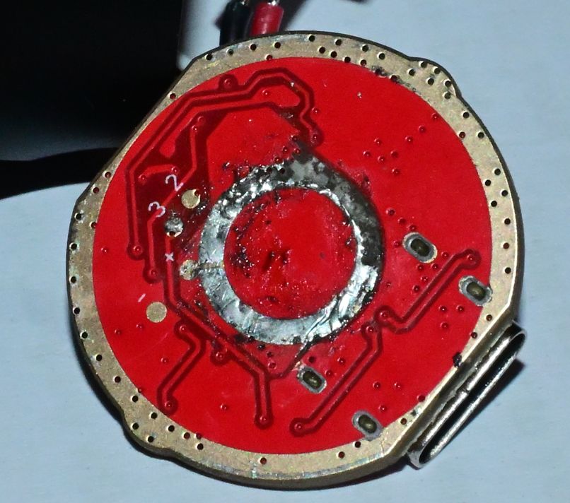
The rather shoddy desoldering job I did with an iron

For replacing the spring, you'll need a 9mm battery spring. I only managed to find them on AliExpress (I can't yet speak to the longevity of these particular ones), so it was a bit of a wait before I could find out if this would even work. Thankfully once they did arrive, they were the right size.

For attaching the spring to the central contact, I highly recommend hot air if at all possible. I tried using a soldering iron, thinking it would work out, but I didn't get a connection I was happy with, plus it was a bit off-centre. Reflowing it with hot air whilst pushing down on the spring gave me a result I was far happier with. Be careful not to get solder on the outer ring of the PCB – it needs to make contact with the body tube to provide the negative connection to the battery, so you want that to be as flat as possible. I got a little bit of solder on mine, but desoldering braid got it off to a good enough standard.

My first attempt at attaching the spring 
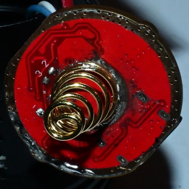
The off-centre first attempt at attaching the spring using a soldering iron

Once you've soldered it, it's worth checking you don't have a short between the spring and the surrounding ring, because that would be a Bad Thing, and it's also probably worth trying out the light just via USB to see if you've broken it. Once you're happy with the outcome, putting it back together is pretty much the inverse of taking it apart. Be aware that you do have to tighten the body tube up a fair bit for it to make a good contact with the PCB, so if it's not working, try tightening it more.

Note: by its nature, the fixes here (other than waiting for updates) require you to be comfortable enough with the command line to follow along. I hope I've at least written the explanation of why this has happened clearly enough to not need any deep knowledge though.

If you're one of the few people like me still using an Xbox 360 wireless controller on your Linux PC, you may have recently noticed your D-pad going all wrong. Left is up, up is left, right is down, and down is right. This will probably have coincided with getting a new kernel, starting with 6.17.

Why it's wrong

For some reason, back in the day, when Xbox 360 controller support was being added to the Linux kernel, wired controllers mapped the D-pad as axes on a hat, and wireless controllers mapped them as separate buttons. For some reason, the D-pad buttons were given BTN_TRIGGER_HAPPY1 to BTN_TRIGGER_HAPPY4. (It seems that the HAPPY events are generic joystick events, rather than meaning anything specific, which answers a question I've been vaguely wondering about for a long time.)

In Linux 6.17, this was changed to report BTN_DPAD events. This is all good and makes sense. Now the controller is actually reporting what's being pressed, not some arbitrary button presses you need to know how to map.

Unfortunately/fortunately (depending on how you look at it), we now have SDL, the layer that basically everything game-related on Linux uses. It has a specific hardcoded mapping for the Xbox 360 wireless controller, plus several more entries in a more general controller database for good measure. This would be fine, but the change to the kernel has also changed the order in which SDL sees the buttons. Thankfully this has only affected the D-pad though, rather than changing all of the buttons around.

However, good news! As of January 2016, the kernel driver has fixed the weirdness with wireless controllers by reporting both a hat and the buttons. More good news! SDL has functionality to automatically generate a mapping for a game controller, and it works with both the old xpad code and the new one. We just need to get rid of the old mappings which don't work any more.

How to fix it

(This has been rewritten a bit from the first version of this blog post as I learned more)

In terms of fixing this out of the box, I've already submitted pull requests to SDL (SDL3, SDL2), which were merged, but then the SDL2 one was reverted until there's more testing with SDL3. This does unfortunately mean that Xbox 360 wireless controllers will continue to be broken with newer Linux kernels, even with new releases using SDL2, but hopefully the SDL2 change can go back in before too much longer.

Unfortunately, even once SDL has a release, and Valve and your distro have packaged it, that still won't magically fix everything without any work. Games tend to ship their own libSDLs, or even have it statically compiled in, rather than relying on Valve's or the OS's. On the plus side, once SDL has been updated (or if you manually remap the controller in Steam), games in Steam should be fine if you're using Steam Input – that kicks the controller handling up the stack slightly, and so they should transparently start to work properly again.

There are, of course, games and applications using SDL that aren't Steam-based, plus it'll still be a while until SDL is updated. I have three possible solutions for that, two of which don't rely on SDL being updated.

Option 1 – Specifying your own mapping

As long as you're using Steam Input for Steam games, this section should really cover you for pretty much everything.

There are a few ways of getting your own controller mappings into games. The easiest and most reliable option is to set the SDL_GAMECONTROLLERCONFIG environment variable, e.g.:

export SDL_GAMECONTROLLERCONFIG="0300a81c5e040000a102000000010000,Xbox 360 Wireless Controller,a:b0,b:b1,x:b2,y:b3,back:b6,guide:b8,start:b7,leftstick:b9,rightstick:b10,leftshoulder:b4,rightshoulder:b5,dpup:b11,dpdown:b12,dpleft:b13,dpright:b14,leftx:a0,lefty:a1,rightx:a3,righty:a4,lefttrigger:a2,righttrigger:a5,platform:Linux,"

Unfortunately, I've had issues getting this to make its way through the Steam runtime. I'm sure it's possible, I just don't know how to do it, and a quick web search didn't help me. On the other hand, launching Steam with this environment variable set does fix Steam itself, so Steam Input now shows the correct D-pad directions without having to go in and manually remap them!

The other alternative is to put the same kind of configuration in a file called gamecontrollerdb.txt in the game's directory. This isn't inherently loaded by SDL, but most games seem to pick up on it.

In both cases, the third-party SDL_GameControllerDB has information on how to generate these mappings, although my one above should work for you.

Option 2 – Deleting or replacing the old libSDL

This works once you've either built a new libSDL yourself, or your distro/Valve have updated theirs. For games that bundle their own libSDL, you should be able to either delete it or replace it with a newer copy. That's all there really is to say about this one. Unfortunately quite a few games (including those built with the Godot engine, for example) statically link SDL, which means there is no separate library to trivially replace.

Option 3 (cursed) – Edit the binaries to fix the mapping

For statically linked binaries (and old versions of libSDL, if you feel like it), I've realised that there is a somewhat cursed way of doing it. I do not provide any guarantees that this is a sensible thing to do. It is definitely using the wrong tool for the job. However, with the controller mapping being text, and both the old and the new D-pad buttons having double-digit numbers, you can run the following sed command on the relevant game binary (try grepping for the original string if you don't know which one is the relevant binary):

sed -i.bak 's/a:b0,b:b1,back:b6,dpdown:b14,dpleft:b11,dpright:b12,dpup:b13,guide:b8,leftshoulder:b4,leftstick:b9,lefttrigger:a2,leftx:a0,lefty:a1,rightshoulder:b5,rightstick:b10,righttrigger:a5,rightx:a3,righty:a4,start:b7,x:b2,y:b3,/a:b0,b:b1,back:b6,dpdown:b12,dpleft:b13,dpright:b14,dpup:b11,guide:b8,leftshoulder:b4,leftstick:b9,lefttrigger:a2,leftx:a0,lefty:a1,rightshoulder:b5,rightstick:b10,righttrigger:a5,rightx:a3,righty:a4,start:b7,x:b2,y:b3,/g <filename>

This does, however, have one potential casualty: the “Razer Onza Classic Edition”. If you have one of these and it's working fine, you might want to be more selective.

The other option

Alternatively you can skip all of this headache and give yourself an entirely different headache by manually building the old xpad driver against your newer kernels. This is also a viable option. I don't know if it's a more or a less tedious option than the alternative.

Welcome to the debut entry on “Dave's Stuff That Needs To Go Somewhere”, the place for me to write things that are possibly actually useful to people and so should exist somewhere other than just on my Mastodon account or similar.

The problem

Anyway, on to the subject of this post: the Netgear GSS116E switch. This is a 16-port managed gigabit switch. I was having some issues with mine, so I did a firmware update on it, and that entirely fixed those issues by making it inoperable.

Opening the switch up and getting at the flash module inside isn't too difficult – there's a whole load of little screws on the back to remove first, then there are a few on the inside that need to be removed to get the main switch PCB out. If I had this blog when I was doing it, I would've documented it better.

The flash module is an MX25L3206E SOP-8 package. It's located near some pin headers. I desoldered it and read it in a TL866II programmer. Running strings on the image seemed to show why it wasn't particularly happy:

Content-Disposition: form-data; name="fileField"; filename="GSS116E_LOADER_V1.0.0.5.bin"
Content-Type: application/octet-stream

I'm going to assume that the existing firmware didn't strip out the appropriate HTTP headers before writing the flash.

Anyway, I tried various different attempts to fix this in varying ways, none of which actually worked, then I put it away for a year.

The fix

Eventually I found another used GSS116E going for relatively cheap on eBay. Pulling the flash chip off this one gave me a good dump to compare with. Unsurprisingly it didn't have HTTP headers sitting at the top, but my initial attempts to understand what it was doing didn't work out, and so I gave up for a little while.

When I got the drive to look at it again, I realised that the beginning of the good flash image contained the string 10050, which I knew was a version number. I then realised that was the version number for the loader, which is what you're meant to flash first when upgrading from an older firmware release. Doing a bit more searching, I then realised that the firmware image proper starts at 0x50000 in the image. Sure enough, using the latest firmware release, taking the loader firmware, appending the actual firmware at 0x50000, flashing that, and doing a factory reset for good measure ended up with a happy switch! Equivalent commands to replicate this from scratch would be something like:

cp GSS116E_LOADER_V1.0.0.5.bin newfirmware.img
dd if=GSS116E_V1.6.1.7.bin of=newfirmware.img seek=640

Anyway, now I have two working GSS116E switches I'm not using instead of just one!

Footnote

Added note: I'm sure I found something about reverse engineering the firmware of the GSS108E, which I now... can't find, but that switch seems to use a completely different architecture, so none of this is likely to be relevant to it.